Back Side Incinerator Structure AutoCAD Drawing with 590 Unit Width
Description
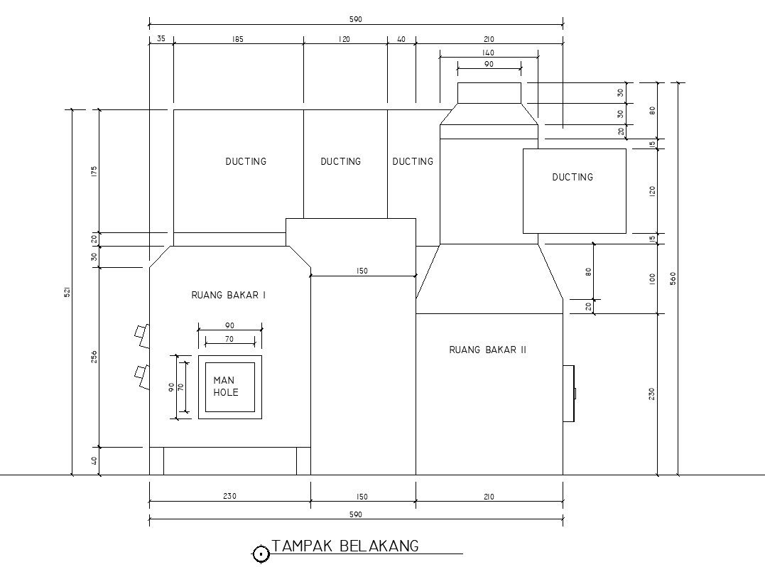
This Back Side Incinerator Structure AutoCAD drawing presents a precise 2D rear elevation prepared for industrial and mechanical layout planning. The drawing clearly illustrates the complete backside configuration with an overall width of 590 units, divided into key functional components such as Ruang Bakar I, Ruang Bakar II, and the connected ducting systems. Dimension annotations define chamber widths of 230, 150, and 210 units, along with vertical height references reaching approximately 560 units. The rear elevation details duct transitions, exhaust outlet alignment, structural offsets, access panels, and a manhole opening measuring about 90 by 70 units. Clean line work, proportional geometry, and clear labeling make the drawing suitable for understanding equipment layout, structural relationships, and maintenance access requirements.
This Incinerator Back View AutoCAD drawing is suitable for architects, civil engineers, plant planners, and builders working on waste management and industrial facility projects. The drawing supports accurate equipment positioning, service clearance evaluation, and coordination with plant layouts, structural frames, and utility routing. Prepared in AutoCAD DWG format, it allows smooth integration with AutoCAD, Revit, SketchUp, and 3D Max workflows for further detailing, coordination, or visualization. The clear dimensional information and organized drafting help ensure consistent interpretation, making this drawing a reliable reference for industrial incinerator structure planning and technical documentation.
File Type:
DWG
File Size:
8.8 MB
Category::
Mechanical and Machinery
Sub Category::
Factory Machinery
type:
Gold
Uploaded by:
viddhi
chajjed
